Shot blaster
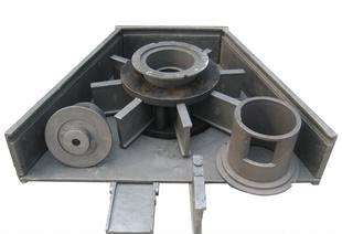
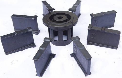
The double discs in the shot blaster are riveted together to form the impeller body. The impeller body is equipped with eight blades, and the impeller body is installed on the main shaft driven by an electric motor along with the shot splitting wheel located in the center of the shot blasting wheel. The inner lining of the hood is equipped with a protective plate, and the shell is equipped with a directional sleeve and a shot feeding tube. During operation, the shot flows into the shot blaster through the shot inlet tube. The splitting wheel that rotates synchronously with the blade causes the projectile to obtain its initial velocity. The projectile flies out through the window of the directional sleeve and is thrown onto the high-speed rotating blades outside the sleeve. After being further accelerated by the blades, it is projected onto the surface of the cleaned workpiece. Because the synchronous rotation of the splitter wheel and blade ensures no vibration transmission of the projectile to the blade, thereby reducing wear on the blade.
1. Sealing performance of shot blaster
a. The transition zone for incoming and outgoing materials is equipped with multi-layer sealing curtains to prevent abrasive particles from flying out of the inlet and outlet when the workpiece enters.
b. The top opening of the shot blasting chamber is equipped with a manganese steel labyrinth baffle, a double-layer rubber seal, and a sealing brush to prevent abrasive from escaping from the top of the shot blasting chamber.
c. Special grating sensors for identifying workpieces. Ensure that the shot blaster only starts blasting when the workpiece enters the blasting area, avoiding the shot blaster from spinning and splashing abrasive out of the open gap when the workpiece enters the curtain.


